In the telecommunication industry, a successful IPTV headend deployment begins long before the first rack is installed. Recently, the Lanaotek engineering team partnered with the Construction Department of Magyar Telekom (Hungary) to conduct a comprehensive on-site survey for their new IPTV Data Center project.
The goal was simple yet critical: evaluate the physical environment, electrical capacity, and safety facilities to ensure a seamless integration of high-performance IPTV equipment.
1. The Critical Role of a Professional Site Survey
A site survey isn't just a walkthrough; it’s a technical audit. For the Hungary Telecom project, our team followed a rigorous protocol to ensure that the infrastructure could handle the thermal and power demands of modern IPTV headend equipment.
Our Site Survey Checklist Included:
Space & Layout: Verification of equipment room location, cabinet layout diagrams, and anti-static floor height.
Cabling Infrastructure: Evaluation of overhead vs. underfloor cabling, cable tray specifications (layered routing for power and communication cables), and ODF rack positions.
Environmental Control: Testing temperature and humidity stability to prevent hardware degradation.
Power & Grounding: Mapping existing -48V DC power supplies and ensuring proper grounding for safety.
There is a corresponding survey report template for the survey of the IPTV headend equipment room, which mainly includes:
Equipment room name and location
Temperature and humidity of the equipment room
Cabling mode of the equipment room: overhead cabling, underfloor cabling, hybrid cabling
Height of anti-static floor
Type of cable tray: single-layer, double-layer, other types
Height and width of cable tray
Cable routing mode of cable tray: layered routing, same-layer routing
Cabling convention: communication cables on the upper layer and power cables on the lower layer; communication cables on the right and power cables on the left
Installation positions of newly added cabinets and equipment: marked on the equipment room floor plan, with row and column numbers
Type, size and quantity of newly added cabinets
Whether there are obstacles under the anti-static floor at the installation positions of newly added cabinets: obstacles need to be cleared in advance; if they cannot be removed, the installation positions shall be changed
Type, specification and quantity of matching bases for newly added cabinets
Whether new cable trays are required: Yes / No
Specification, quantity and installation positions of newly added cable trays: marked on the equipment room floor plan, with row, column and height information
Whether new ODF racks are required: Yes / No
Specification, quantity and installation positions of newly added ODF racks: marked on the equipment room floor plan, with row and column numbers
Locations of existing ODF racks in the equipment room, positions of interconnected ODF terminals and types of ODF terminals: marked on the equipment room floor plan, with row, column and quantity information
Type, quantity and length of interconnected pigtails
Locations of existing -48V power supplies in the equipment room, positions of interconnected power terminals and types of interconnected power terminals: marked on the equipment room floor plan, with row, column and quantity information
Specification, quantity and length of -48V power cables from existing -48V power supplies in the equipment room to the newly built PDF cabinet
Specification, quantity and length of -48V power cables from newly built equipment cabinets to the newly built PDF cabinet
Locations of existing equipment requiring direct interconnection in the equipment room: marked on the equipment room floor plan, with row and column numbers
Type of connectors, type, quantity and length of interconnection cables for existing equipment requiring direct interconnection in the equipment room
2. Technical Challenge: Solving the 25-Meter Power Drop Issue
During the on-site survey at the Magyar Telekom facility, our engineers identified a significant technical hurdle:
The Problem: The existing -48V power supply was located 25 meters away from the newly designed PDF (Power Distribution Frame) cabinet. Standard telecom installations typically keep this distance under 10 meters to minimize voltage drop.
The Lanaotek Solution: With 9 equipment cabinets, each consuming 3000W (a total load of 27,000W), the maximum current was calculated at 562.5A. A standard cable would result in excessive heat and power loss over 25 meters.
To ensure long-term stability and power supply safety, our team calculated the necessary voltage compensation and recommended two 120mm² -48V power cables as the input for the PDF cabinet. This adjustment was approved by the customer and integrated into the final production plan.
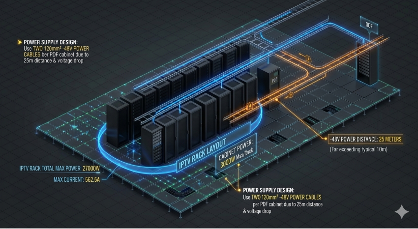
All other survey items in this on-site survey went smoothly, except that the -48V power supply was 25 meters away from the newly built PDF cabinet matching the IPTV headend equipment, far exceeding the conventional distance of 10 meters.
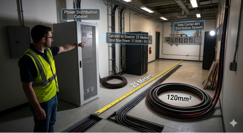
There are 9 equipment cabinets in total for this IPTV headend equipment site, with a designed maximum power consumption of 3000W per cabinet and a total designed maximum power consumption of 27000W. The designed maximum current is 27000W / 48V = 562.5A. Considering the voltage drop over the 25-meter distance, it was determined after communication with the customer that two 120mm² -48V power cables shall be used as the input power cables for the newly built PDF cabinet to ensure power supply safety.
After being reviewed and approved by both parties, the survey report was uploaded to the system to guide equipment production and stock preparation.
Need Professional Support for Your Next IPTV Project?
Are you planning a telecom infrastructure upgrade or a new data center build? Contact Lanaotek Engineering Team for a Technical Consultation.
By Lanaotek
Lanaotek specializes in translating cutting-edge optical and Ethernet transmission technologies into clear, valuable insights that help our customers stay ahead in a fast-evolving digital world.
By turning complex technical concepts into practical, business-driven content, we aim to empower decision-makers with the knowledge they need to make confident, future-ready choices.
 EN
EN
 fr
fr  es
es  ru
ru  pt
pt  ar
ar  de
de 
 Internet Data Center
 FAQs
FAQs Industry News
 About Us
 Data Center Switch
  Enterprise Switch
  Industrial Switch
  Access Switch
  Integrated Network
  Optical Module & Cable



 Call us on:
  Email Us:
  2106B, #3D, Cloud Park Phase 1, Bantian, Longgang, Shenzhen, 518129, P.R.C.